
Device Overview
The Gardner Bender GDT‑311 is a compact 3‑function digital multimeter featuring a 3.5‑inch display. It measures AC up to 500 V, DC up to 600 V, and resistance up to 2 MΩ. Manual ranging offers 11 selectable ranges for precise readings. The unit is lightweight, ideal for field work. Portable battery‑operated.
Safety Precautions
Before using the Gardner Bender GDT‑311, read all safety warnings. Keep the meter dry; avoid contact with water or other liquids. Do not exceed the maximum voltage ratings: 500 V AC, 600 V DC, and 2 MΩ resistance. When measuring live circuits, disconnect power if possible. Use insulated probes and wear rubber‑capped gloves. Do not touch the probe tips or the display while the meter is powered. Avoid short‑circuits by ensuring the probe leads are not touching each other or conductive surfaces. Do not use the meter in explosive atmospheres unless it is rated for such use. For AC measurements, select the correct range (200 V or 500 V) to prevent over‑voltage damage. When measuring DC, use the 600 V range. When measuring resistance, ensure the circuit is powered off to avoid false readings. Do not exceed the battery voltage; use only the supplied batteries. Store the meter in a dry place, away from extreme temperatures. If the meter displays “0” or “OL” repeatedly, check the leads for damage and replace them if necessary. For any malfunction, consult the manufacturer’s support. Keep the meter out of reach of children. Follow local electrical codes and regulations. If you are unsure, seek professional assistance. The GDT‑311 is not a substitute for a qualified electrician’s tools.
When operating the meter, ensure the probe leads are connected and the contacts are clean. Do not use the meter to test high‑current circuits beyond its rating; use a ammeter. Never attempt to repair the meter yourself; contact service. Keep the meter’s battery compartment sealed and replace batteries only with the correct type fast.
Features
The Gardner Bender GDT‑311 is a lightweight, battery‑powered digital multimeter designed for versatility and ease of use. It offers three core measurement functions: AC voltage, DC voltage, and resistance. The meter supports 11 manual ranges, allowing users to select the most appropriate range for accurate readings and to avoid over‑voltage or over‑current conditions. The 3.5‑inch LCD display provides clear, high‑contrast readouts, and the rotary dial enables quick range selection. AC voltage measurement is available up to 500 V, with a dedicated 200 V setting for finer resolution on lower‑voltage circuits. DC voltage can be measured up to 600 V, while resistance measurement extends to 2 MΩ, making the GDT‑311 suitable for a wide array of electrical diagnostics. The device is powered by standard batteries, eliminating the need for external power supplies and making it ideal for field work. Its compact form factor and durable construction allow for reliable operation in a variety of environments, from residential wiring to industrial equipment testing. The GDT‑311’s manual ranging feature gives users full control over measurement accuracy, while the clear display and intuitive interface reduce the likelihood of user error. Overall, the GDT‑311 delivers dependable performance, portability, and a straightforward user experience for both hobbyists and professionals alike.
The meter runs on four AAA batteries. Its ABS housing resists drops. Probe leads are 3 ft long with gold‑plated connectors. A 10 A fuse protects against shorts. A non‑contact voltage indicator warns of live AC. Auto‑zero calibration keeps resistance accurate. The interface is simple, with a single rotary dial and LED backlight. The device also includes a quick‑release feature for easy lead changes!!!
Controls and Interface
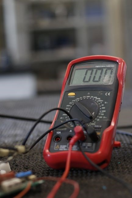
The Gardner Bender GDT‑311 features a single rotary dial that serves as the primary control for selecting measurement functions and ranges. The dial is labeled with the three functions: AC, DC, and Ω. Turning the dial clockwise advances through the available ranges for each function, while turning it counter‑clockwise returns to the previous range. A small LED indicator on the dial’s face lights up to confirm the selected function, and a second LED on the back of the meter illuminates when the device is powered on.
Power is supplied by four AAA batteries, inserted into the battery compartment located on the back of the meter. A removable cover protects the contacts and allows for easy battery replacement. The meter’s front panel includes a 3.5‑inch LCD display that shows the measured value in real time. The display is backlit, ensuring visibility in low‑light conditions, and it automatically clears after a brief period of inactivity. The display also shows the selected range and the function indicator.
The probe connectors are gold‑plated and rated for 10 A, providing reliable contact with a wide variety of test points. The leads are 3 ft long and have a quick‑release mechanism that allows for rapid connection and disconnection. The meter’s housing is made of ABS plastic, offering durability and resistance to impact. A non‑contact voltage detector is integrated into the front of the meter, giving a visual cue when a live AC source is present. The overall interface is designed for intuitive use, with minimal buttons and clear labeling to reduce user error. Ensuring measurements daily. The ergonomic design ensures comfortable handling during extended measurement sessions daily.

Display and Readings
The Gardner Bender GDT‑311 sports a 3.5‑inch LCD display that presents measurement values in real time. The screen is backlit for visibility in low‑light conditions and automatically clears after a short period of inactivity. When a function is selected, a small LED on the dial lights up to confirm the mode (AC, DC, or Ω). The display also shows the current range, allowing the user to verify that the selected range matches the expected measurement magnitude.
For AC voltage, the meter can read up to 500 V, with two dedicated ranges: 200 V and 500 V. The 200 V range offers higher resolution for lower voltages, while the 500 V range accommodates higher mains or industrial voltages. DC voltage readings extend to 600 V, and the resistance function covers up to 2 MΩ. The manual‑ranging rotary dial provides 11 discrete ranges across all functions, enabling precise selection for each measurement type.
Values are displayed in a clear numeric format, with decimal points and appropriate units (V for voltage, Ω for resistance). The meter’s firmware automatically switches to the most suitable range when the dial is set to “Auto” (if available), but the GDT‑311 relies on manual selection for optimal accuracy. The display updates continuously as the probe contacts change, giving instant feedback during circuit testing.
When measuring resistance, the meter displays values in ohms, with the ability to read fractional values for low resistances. For example, a 10 Ω resistor will show 10.00 Ω, while a 1 MΩ resistor will appear as 1,000,000 Ω. The display also indicates when the resistance exceeds the maximum range by showing “>2MΩ.” Similarly, for voltage measurements, the meter displays “>500 V” or “>600 V” when the input exceeds the selected range. This prevents misreading of over‑voltage conditions. The GDT‑311’s firmware includes a 0.5 % accuracy specification for voltage and 1 % for resistance, ensuring reliable data for professional use. The display’s refresh rate is fast enough to track rapid changes, making it suitable for dynamic circuits. Users can also observe the decimal point shift when the measured value crosses a new order of magnitude, providing visual confirmation of the measurement scale. The combination of a large, backlit screen, clear numeric output, and range indicators makes the GDT‑311 a dependable instrument for both field and laboratory applications at 1 Hz

Manual Ranging and Range Selection
The Gardner Bender GDT‑311 is designed for manual range selection, giving users full control over measurement precision. The device features a 14‑position rotary dial that allows the operator to choose from 11 distinct ranges across its three functions: AC voltage, DC voltage, and resistance. For AC voltage, the available ranges are 200 V and 500 V, with the 200 V setting providing higher resolution for lower‑voltage measurements. DC voltage ranges extend up to 600 V, while resistance can be measured up to 2 MΩ. Selecting the correct range is critical; an improperly chosen range can lead to inaccurate readings or even damage the meter. The dial’s LED indicator lights up to confirm the selected range, and the display shows the current range setting for quick verification. Users should always match the expected input magnitude to the appropriate range before taking a measurement. When measuring high‑voltage circuits, the 500 V AC and 600 V DC ranges should be used, whereas low‑voltage signals are best captured with the 200 V AC or the lowest resistance range. The manual ranging feature also allows for fine‑tuned measurements in complex circuits where automatic range selection might not be available or desired. By manually selecting the range, technicians can avoid the “overrange” warning and ensure that the meter’s resolution is maximized for the specific test scenario. The GDT‑311’s manual control is especially useful in fieldwork, where quick adjustments are necessary and the environment may require precise, repeatable measurements. Proper range selection enhances both accuracy and safety, making the GDT‑311 a reliable tool for professionals who need to tailor each measurement to the exact conditions of their work.
When the dial’s LED turns green, the selected range is suitable; a red light indicates an over‑range condition, protecting the meter. The firmware also remembers the last used range, allowing quick resumption of prior settings. This feature saves time during complex diagnostics!!
Measuring AC Voltage
The Gardner Bender GDT‑311 offers two AC voltage ranges: 200 V and 500 V. For accurate readings below 200 V, select the 200 V setting; for higher mains voltages, use the 500 V range. The meter’s analog‑to‑digital converter samples the waveform at a rate sufficient to capture 50/60 Hz mains signals without distortion. Connect the red probe to the positive phase and the black probe to neutral or ground; The meter displays the RMS value automatically, and the LED confirms the range. If the input exceeds the selected range, the display shows “OL” (over‑limit) and the LED flashes red, protecting the internal circuitry. Manual ranging avoids the automatic range feature, which may lock into a higher range and reduce resolution. Use a stable, isolated power source to prevent stray currents. The GDT‑311’s built‑in surge protection limits the voltage applied to the input pins, safeguarding both the user and the instrument. The “hold” function freezes the current reading on the display. The 3.5‑inch LCD provides a clear, backlit readout, showing the value in volts with two decimal places. Always verify that the meter is set to the correct AC mode before connecting the leads, as the GDT‑311 also measures DC voltage and resistance. By following these steps, technicians can obtain reliable AC voltage measurements in a variety of field and laboratory environments.
Calibration of the AC measurement range is performed during manufacturing, with a tolerance of ±2 % for the 200 V range and ±3 % for the 500 V range. Users can verify calibration by comparing the meter’s reading against a known reference source, such as a calibrated AC voltage generator. If a discrepancy greater than the stated tolerance is observed, the meter should be serviced by an authorized Gardner Bender technician. The GDT‑311 includes a built‑in auto‑zero function activated by pressing the ZERO button while in AC mode; this feature compensates for residual offset caused by stray electromagnetic interference. For high‑frequency AC signals (above 1 kHz), the meter’s bandwidth limitation may result in lower accuracy, so it is recommended to use the GDT‑311 only for standard mains frequencies. The device’s ergonomic design, with a recessed probe tip and a comfortable grip, allows for prolonged use without fatigue. When measuring AC voltage in hazardous environments, ensure that the meter is rated for the appropriate voltage class and that all safety protocols are followed. The GDT‑311’s durable housing and sealed connectors protect against dust and moisture, making it suitable for outdoor and industrial applications. The meter’s battery indicator informs the operator when a replacement is needed, ensuring continuous operation.
Measuring DC Voltage
The Gardner Bender GDT‑311 offers a dedicated DC voltage mode with a maximum of 600 V. Select the appropriate range by turning the manual dial to 200 V, 400 V, or 600 V; the lowest range above the expected voltage provides the best resolution. The meter’s ADC samples the DC input and displays the value on the 3.5‑inch LCD with two decimal places. Press the ZERO button while in DC mode to compensate for any offset introduced by the leads. The HOLD button locks the current reading, useful when comparing multiple points. Connect the red probe to the positive terminal and the black probe to the negative or ground. The internal protection limits input to 600 V; exceeding this limit shows “OL” and flashes the red LED. Calibration is factory‑set to ±2 % accuracy; verify against a known reference voltage. If a larger discrepancy appears, contact Gardner Bender support. This DC mode is ideal for checking battery outputs, power supplies, and circuit voltages in both laboratory and field settings.
The meter’s 3.5‑inch display remains backlit for low‑light conditions, and the device’s battery indicator alerts when power is low. For high‑current DC measurements, the meter’s internal series resistor limits current to protect the circuitry. The GDT‑311 also supports auto‑zero in DC mode, which can be toggled via the menu for fine‑tuning. Users should periodically check the probe contacts for corrosion, as this can affect accuracy.
The device’s rugged casing ensures durability during field use and reliability.
for all use.

Measuring Resistance
The Gardner Bender GDT‑311 measures resistance from 200 Ω to 2 MΩ. Switch the dial to RES and pick a range: 200 Ω, 500 Ω, 1 kΩ, 2 kΩ, 5 kΩ, 10 kΩ, 20 kΩ, 50 kΩ, 100 kΩ, 200 kΩ, or 2 MΩ. Connect the red probe to the test point and the black probe to reference. The meter supplies a low‑current test signal; the display shows resistance with two decimal places. Press ZERO to compensate lead resistance. The HOLD button freezes the reading. If the resistance exceeds the chosen range, the display shows “OL” and the red LED flashes. Use the 2 MΩ range for high‑value resistors to avoid loading. The device’s rugged enclosure protects the circuitry during field use.
When measuring components like thermistors or resistors, select the highest range to maintain accuracy. The GDT‑311’s display is backlit for low‑light conditions, and the red LED indicates a successful connection. If the meter shows “OL” or “0.00”, check for open circuits or disconnected leads. The device supports a ZERO function to subtract lead resistance. The manual ranging allows users to lock in a specific range, preventing accidental auto‑range changes during sensitive measurements. The meter’s battery life is rated for up to 500 hours on a single CR2032 battery.
When measuring resistance in a circuit that may be powered, first disconnect power to avoid damaging the meter. The GDT‑311 includes a safety feature: if a voltage is detected while in resistance mode, the meter will display “VOLT” and the red LED will flash, measurement of a circuit.!!

Using the Meter in Practice
When deploying the Gardner Bender GDT‑311 on a job site, begin by verifying the battery status; the unit uses a single CR2032 and displays a low‑power warning when the voltage drops below 2.0 V. Connect the probes to the circuit, ensuring the black lead touches the reference point and the red lead the test point. For voltage measurements, select the appropriate AC or DC range and observe the display; the meter’s auto‑zero feature will eliminate lead resistance. In resistance mode, lock the dial to the highest range to avoid “OL” indications on high‑value components. The HOLD button freezes the reading, allowing you to record values without the display changing. The meter’s backlit screen and red LED provide visibility in low‑light conditions, while the ZERO function corrects for lead resistance. If a voltage is present while in resistance mode, the meter will display “VOLT” and flash the red LED, preventing accidental damage. For continuity checks, switch to the CONT mode; a beep confirms a closed circuit. The GDT‑311’s rugged enclosure protects the internal circuitry from accidental drops and moisture, making it suitable for outdoor use. Always disconnect power before measuring resistance to avoid false readings or meter damage. Document each measurement by noting the range, reading, and any zero adjustments. The device’s manual ranging allows precise selection of ranges for delicate components such as thermistors or high‑value resistors. Finally, after completing measurements, turn off the meter to conserve battery life, and store it in a dry, temperature‑controlled environment to maintain accuracy. Use the meter’s built‑in safety features to protect yourself. Now
Troubleshooting Common Issues
When the Gardner Bender GDT‑311 shows “0” or a blank screen, first check the probe
connections. The black lead must be firmly seated in the COM terminal and the red
lead in the correct VΩ terminal; loose contacts often cause a zero reading.
If the display remains blank, inspect the battery. A depleted CR2032 will trigger
the low‑power indicator and disable the meter. Replace the battery with a fresh
one and confirm the indicator turns off.
“OL” (over‑limit) errors on voltage or resistance indicate that the selected range
is too low. Manually rotate the dial to the next higher range until the reading
stabilizes. In resistance mode, an “OL” may also mean an open circuit; verify
that the test leads are connected to a conductive path.
If the meter displays a constant “VOLT” or “AMP” while in resistance mode, the
device is detecting stray voltage. This can happen when the red probe contacts
a live conductor while the black probe is grounded. Switch to the correct mode
and double‑check probe placement. The meter’s auto‑zero feature will correct for
lead resistance, but stray voltage will still trigger the “VOLT” indicator.
During a continuity test, a continuous beep indicates a closed circuit.
If the beep is absent, the circuit is open or the probe contact is poor. Ensure
the probes touch the test points firmly. The GDT‑311’s continuity mode uses a
1 kΩ reference resistor; if the measured resistance is below 1 kΩ, a beep will
sound. A lack of beep may also signal a battery issue, so double‑check the power
status.
Inconsistent measurements often result from electromagnetic interference.
Nearby high‑current cables or radio transmitters can induce noise. Move the
meter away from such sources or use a shielded probe cable. The GDT‑311’s internal
filtering mitigates most interference, but extreme environments may require a
dedicated test setup.
If the meter’s backlight fails to illuminate, the internal LED may have burned
out. This does not affect measurement accuracy but reduces readability. Contact
Gardner Bender support for a replacement or repair kit.
For users who notice the display flickering or showing random numbers, check
for stray voltage on the leads. A short between the red and black probes should
display zero volts and produce a beep in continuity mode. If the reading deviates,
the internal circuitry may be damaged and the unit should be returned for
service.
Keep the meter clean, avoid exposing it to moisture, and store it in a dry
environment to prevent future errors. Following the manufacturer’s safety
guidelines and using the meter within its specified voltage and resistance limits
will minimize the likelihood of encountering these common issues.

Warranty and Support
The Gardner Bender GDT‑311 is backed by a standard one‑year limited warranty that covers manufacturing defects and workmanship. The warranty applies only to the original purchaser and excludes damage caused by misuse, accidental impact, or exposure to extreme temperatures. To file a claim, contact Gardner Bender customer support at 800‑624‑4320 or visit the support portal at gardnerbender.com. Provide the serial number, proof of purchase, and a brief description of the problem. For international customers, shipping of a replacement unit may incur additional costs; the company will supply a prepaid shipping label if the defect is verified.
Technical assistance is available 24/7 via phone, email, and live chat. The support team can walk users through troubleshooting steps, firmware updates, and calibration procedures. The GDT‑311 can connect to a PC through the included USB interface for advanced diagnostics, firmware flashing, and detailed log retrieval. Gardner Bender also offers an online knowledge base with FAQs, user forums, and downloadable PDF manuals. Product registration on the website provides warranty status updates and product alerts.
In case of a defect, the company will repair the unit, replace it with an equivalent model, or issue a refund, depending on the customer’s preference and the nature of the fault. All repairs are performed at authorized service centers or by the manufacturer’s technicians. The warranty does not cover accessories, batteries, or third‑party components. Replacement batteries are sold separately and are not covered under the warranty unless they fail due to a manufacturing defect. For extended protection, customers may purchase the Gardner Bender Extended Warranty Plan, adding two additional years of coverage and priority support.
To keep the warranty valid, retain the original packaging and documentation. Do not alter the device’s casing or internal components. If the device is used in hazardous environments, consult the safety guidelines before deployment. For any questions, the support team is reachable at support@gardnerbender.com or by calling the toll‑free number listed above. Warranty claims are processed within 14 business days, and customers receive a tracking number once the replacement is shipped.
Leave a Reply